Network Analyzer
When we want to build some electronic circuits, the first measuring device that we need is a voltmeter.
Then, very quickly, we need an oscilloscope (to see why our circuit does not work).
Very often, we need to measure the behavior of some components at different frequencies : resistors, capacitors, inductances, filters, crystal quartz … etc ; or we need to study the stability of a control loop.
One of the best way to do these measurements is to use a network analyzer.
Commercial network analyzers are very sophisticated, very powerful, but also very expensive.
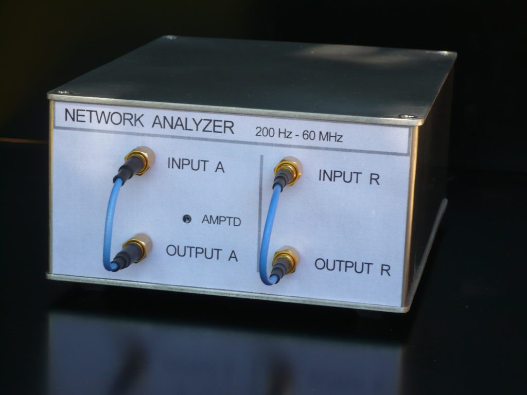
So, we tried to build a small network analyzer.
The network analyzer we will describe here, is mainly a sine wave generator driven by a personal computer (PC) and a voltmeter connected to the same PC.
The voltmeter is like a synchronous detector, it measures the amplitude and the phase of the signal at the frequency of the generator.
The frequency range is from 200Hz to 60MHz, the frequency resolution is approximately 0.035 Hz.
With some restrictions, it is possible to extend the frequency range down to 20 Hz.
The network analyzer measures the gain and the phase (or the group delay) of filters and amplifiers (versus frequency). The gain scale is linear or logarithmic (dB scale); the frequency sweep is linear or logarithmic.
The network analyzer measures impedances , it can display :
– the module and the argument (phase) of the impedance .
– the real part and the imaginary part of the impedance.
– the module and the phase of « S11 »
– for a capacitor, the value of the capacitor and the quality factor (Q) ,with the series model or with the parallel model.
– for an inductor, the value of the inductor and the quality factor (Q), with the series model or with the parallel model.
The PC drives the network analyzer with an USB port.
On this site, you can find the description and the electrical schematics of this analyzer.
The programs to run this analyzer are also available (for linux and windows).
Here are some measurements :

Impedance measurement of a 16 MHz quartz crystal
I like to look at this beautiful curve !
With this measurement and with the measurement of the capacitance of the crystal quartz (far from the resonances), we can find the equivalent schematic of the quartz crystal.
Impedance at the input of a coax cable, the output is open:
(The scale for the impedance is log, the scale for the phase is linear)
The length of the cable is 8m, the position of the maximas and the minimas is an indication of the cable length.
This measurement can help to find the position of a defect on a cable.
Impedance measurement of a 10nF capacitor (polypropylene):
This measurement is made without calibration.
When the measurement is finished you can change the scales and the display formats.
The measurement can be saved as a picture (a .bmp file, 1024*768)
Or the measurement datas can be saved in a file with the extension .s1p (for a one port device), or .s2p (for a two ports device).
This file can be read by a s-parameter simulation software (as Qucs, RFSIM99 for example).
Two low-pass filters (10MHz and 20MHz)
The same low-pass filters , but now the two filters are in series (the scale is 20dB/division).
The description of the analyzer, the electrical schematics, and some indications to use the programs: anaresoanglaisusb.pdf
The programs for windows: network_analyzer_windows.zip
The programs for linux (UBUNTU) : network_analyzer_linux.zip
The programs for the ATmega168 : prog_atmega-2.zip
The printed circuits as pdf files : printed_circuit.zip
Somes photographs of the boards.

Measurement accessories : measurement_accessories.pdf
Measurement files : measurement_files.zip
Some links :
http://www.arduino.cc/ (an USB interface)
http://www.lancos.com/prog.html (PonyProg software)
http://n2pk.com/ (A network analyzer with a very good documentation.)
http://www.linear.com/designtools/software/switchercad.jsp
(a SPICE simulation software (LTspice), with this software we can simulate some parts of our analyzer.)
http://groups.yahoo.com/group/LTspice (LTspice users group, useful to get the spice model of some components (MC1496))
http://www.memresearch.com/download.htm (to get the freeEM3DS software, the 150MHZ filter is designed with this software)
http://qucs.sourceforge.net/
Qucs, briefly for Quite Universal Circuit Simulator, the software aims to support all kinds of circuit simulation types, e.g. DC, AC, S-parameter, Harmonic Balance analysis, noise analysis, etc.
http://electroschematics.com/835/rfsim99-download/
(RFSim99 is a free S-parameter based circuit simulator)
http://contact.tm.agilent.com/Agilent/tmo/an-95-1/ (An application note by HP on S-Parametre Techniques)
http://www.wetterlin.org/sam/PortView/PortOverview.htm (PortView is a Windows program for viewing and manipulating one-port and two-port S-parameter data.)